Embedded software development and testing process has the following steps:
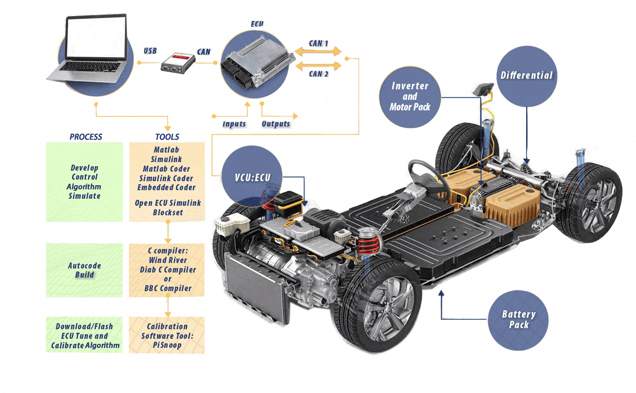
- Develop the control algorithm in Matlab/Simulink environment. For simulation purposes, develop a “plant” model. Matlab/Simulink code can be further extended with C/C++ functions using the S-functions interface.
- Simulate, debug, test, and evaluate the control system in the non-real-time, Laptop’s Matlab/Simulink environment.
- Auto-code the control algorithm for the Target ECU: generates C code.
- Build the C code for the target ECU and generate executable code: using the C Compiler tool.
- Download/Flash the executable code to ECU: using the Calibration and Tuning Software tool.
- Run the code on the ECU, tune, calibrate, test, and validate it while running on the ECU, using the Calibration and Tuning Software on the Laptop PC.
Software Tools

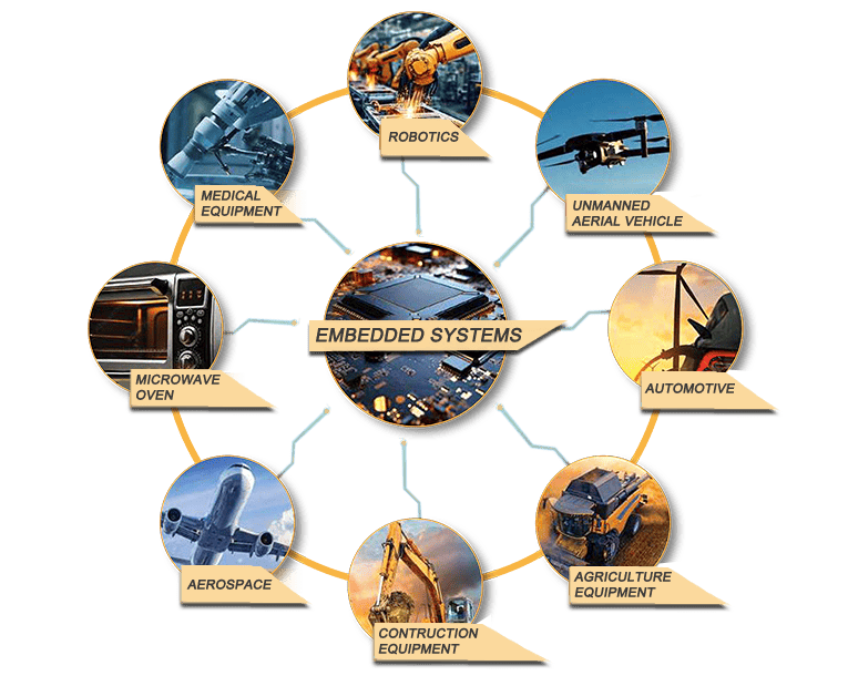
Embedded software is the vital component that is the “brains” in all of the devices used in our civilization, from microwave ovens, cars, tractors to airplanes. Embedded software is the program that runs on the embedded controller hardware, referred to as ECU (electronic control unit) or ECM (electronic control module), which is a printed circuit board (PCB) in one package that includes a microcontroller, IO interface, and often power amplifier circuits. The exact content and shape of the ECU vary depending on the application market, i.e. ECUs used in vehicle applications are different that the ECUs used on microwave ovens or medical equipment. The smarter the functionalities of the device, the more sophisticated the embedded software needs to be.
As systems become more and more complex, so do the complexity of embedded software. For instance, the embedded software on a microwave oven is much simpler that the embedded software on a self driving car. Equally important aspect of embedded software development is its testing and validation; how do we make sure it is reliable. Extensive simulation testing technologies are utilized in testing and validation, such as model in the loop (MIL), software in the loop (SIL), hardware in the loop (HIL) testing. Depending on what is at stake (lives or inconvenience), the extend to which embedded software is tested and validated varies in different applications.
Embedded Software versus Non-Embedded Software
- Embedded software deals with real world 10 in real-time. A few seconds or even milliseconds of delay can have serious consequences, including loss of life, in some embedded control applications. Whereas such delays in general software may simply result in inconvenience to the user.
- Embedded software is the “brain” of a device. The smarter the “brain” is, the smarter the device is.
- Embedded software reliability is paramount importance because lives may be riding on it, hence must be tested extensively using exhaustive testing techniques using MIL/SIL/HIL technologies. Non-embedded software generally does not have this strict requirement on reliability.
- As the markets demand more and more sophisticated devices, with more reliability and lower cost, the embedded software development task necessarily becomes more sophisticated, must be reliable, and development cost must be low.
- Security is a fundamental concern for embedded software and embedded computers, since virtually everything will shortly have IIoT connectivity, opening a box for many opportunities as well as security vulnerabilities.
An embedded control software is developed in three main phases

PHASE 1

PHASE 2
HIL testing can be performed by independent engineering teams or companies, providing objective and exhaustive testing. It offers cost savings, better safety, and test repeatability. HIL testing by independent organizations is especially important for OEMs in order to assure impartial testing and validation of their products.

PHASE 3
Various software tools like CANalyzer and CANape are used for HIL testing, enabling monitoring, test condition definition, data collection, and result analysis. These tools facilitate memory read/write access, test plan execution, and automation of test and validation processes.

The Embedded Software Development for the VCU (for that matter, for any ECU) includes the use of following hardware and software tools:
Hardware
- Laptop PC
- USB/CAN Interface Module
Software on the Laptop PC
- Windows 10 (64 Bit)
- Matlab
- Simulink
- Matlab Coder
- Simulink Coder
- Embedded Coder
- Simulink Block Set for ECU Support
- C Compiler (for target ECU i.e. Wind River)
- Calibration and Tuning Software, i.e. CANape by Vector
The embedded software development and testing process consists of several steps, which are as follows:
1. Develop the control algorithm in the Matlab/Simulink environment:
In this step, the control algorithm is designed and implemented using the Matlab/ Simulink software. The algorithm is typically developed using a graphical interface, allowing for easy visualization and manipulation of the control logic.
2. Simulate, debug, test, and evaluate the control system:
Once the control algorithm is developed, it is simulated in the non-real-time environment of a laptop using Matlab/Simulink. This allows for thorough testing and evaluation of the control system’s performance under different scenarios and inputs. Any issues or bugs in the algorithm can be identified and debugged at this stage.
3. Auto-code the control algorithm for the Target ECU:
After the control algorithm has been verified through simulation, it is auto-coded to generate C code. Auto-coding is the process of automatically translating the algorithm from the Matlab/Simulink environment into executable C code that can run on the target Electronic Control Unit (ECU).
4. Build the C code for the target ECU and generate executable code:
In this step, the generated C code is compiled using a C Compiler tool. The compiler translates the human-readable C code into machine-readable binary code that can be executed by the target ECU.
5. Download/Flash the executable code to ECU:
Once the C code is compiled and transformed into executable binary code, it needs to be downloaded or flashed onto the target ECU. This process involves transferring the code from the development environment to the ECU using specialized tools and protocols.
6. Run the code on the ECU, tune, calibrate, test, and validate it:
After the executable code is loaded onto the ECU, the control system is executed on the actual hardware. The system is tuned, calibrated, tested, and validated in real-time using Calibration and Tuning Software running on a laptop PC. This allows for fine-tuning of control parameters, performance evaluation, and validation of the control system’s behavior under real-world conditions. HIL Testing is highly effective before testing on an actual vehicle.
Overall, these steps ensure a systematic approach to developing and testing control systems, starting from algorithm development and simulation, to auto-coding, building, downloading, and finally validating the control system on the target ECU.