Electric Vehicle
Autonomous
Connected
Performance
Updated
Evolving
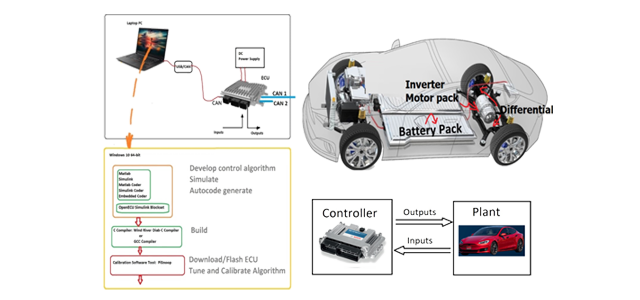
Embedded control software runs on the ECU in real time and defines the logic between inputs and outputs to the outside world; that is the controlled machine, operator interface devices, other networked ECUs. The control algorithm is developed using Matlab/Simulink/Stateflow software tools, simulated off-line, then auto-code generated to C-code, compiled and flashed to the ECU, then calibrated, tuned, tested and validated on the ECU using software tools such as CANalyzer/CANape during HIL and actual machine testing stages.
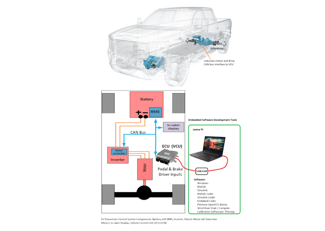
EV powertrain control is one of the essential technologies in this market. EV is powered by electric batteries, and traction power is provided by an induction motor and amplifier called “inverter”. The inverter has the OEM specific induction motion control amplifier circuit as well as built-in microcontroller. The inverter mode is selected in software configuration via CAN bus messages, i.e., torque mode, speed mode. Vehicle Control Unit (VCU) reads the driver pedal and brake sensors and generates the desired command (torque command or speed command) to the inverter via CAN bus messages in real time. Embedded control software that runs on the VCU is therefore critical part of the EVs motion control. In addition to handling driver commands and in cabin information display system (driver related inputs and outputs), and commanding the inverter, the VCU also communicates with the battery management system (BMS) for energy management. The development process for the embedded control software involves MIL, HIL and on prototype EV testing.
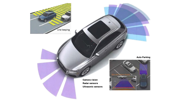
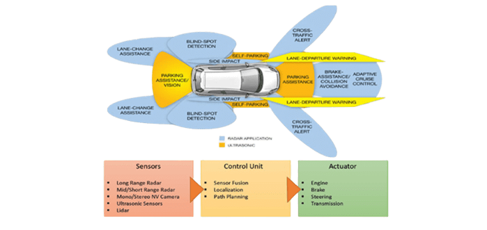
Advanced Driver Assistance System (ADAS)
Functions
